https://www.palomartechnologies.com/blog/the-importance-of-dc-self-bias-voltage-in-plasma-applications
The Importance of DC Self-Bias Voltage in Plasma Applications
In reactive ion etching (RIE) plasma processes, the parameter known as DC self-bias voltage is an important “control knob” for the ion energy. Depending on the specific application, the process engineer can manipulate this parameter for the desired effect. Generally speaking, a higher DC self-bias leads to a higher rate of ion etching.
When an RF electric field is applied to a vacuum chamber, the electrons are driven back and forth by the electric field and hit the powered electrode every alternating half of the RF cycle. A blocking capacitor, normally available in the Tuning Network, acts as conductor for the RF AC field but also acts as an isolator for a self-induced DC field. The impinging of electrons on the powered electrode allow the buildup of a negative DC field in addition to the AC field. This negative potential is the DC self-bias.
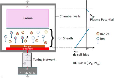
Figure 1 below shows the typical plasma distribution across the chamber and its time-averaged values of electrical potentials in the steady state. In the figure, regions A and B are the “ion sheaths” which are typically a few millimeters-thin layers that sit between the plasma bulk and the electrodes (Chamber walls – Anode and Powered electrode – Cathode).
The sheath thickness is inversely proportional to the plasma density and the process operating pressure.
Figure 1: Illustration of plasma distribution (Grounded Chamber) and electrical potential (Electrode) in a reactive ion etching process.
The plasma bulk is at a higher potential than the electrode. Ions constantly bombard the electrode in response to the potential difference. A large quantity of ions, present in the plasma, cannot react quickly to the RF field but the DC self-bias accelerates them towards the powered electrode. These ions acquire an average energy (eV) equivalent to the sum of DC self-bias Vdc and the plasma potential Vpp (DC BIAS = -Vdc + Vpp) [1].
Factors Influencing DC Self-Bias
The factors that influence DC self-bias are:
- Ratio between the surface areas of the ground and powered electrodes
- Chamber pressure, being that the self-bias is inversely proportional
- RF forward power, being that the self-bias is proportional
- Type of gas
When designing a plasma system, typically the mechanical design of the chamber is driven by factors like product size and quantity, required throughput, type of plasma, and so on. For this reason, once designed, the ratio between the anode and cathode can no longer be changed. This limitation may affect the overall quality of design of the plasma system, as only this factor can make the difference between a highly efficient or poorly efficient system.
--------------------------------
The DC self-bias voltage can be increased by reducing the chamber pressure. Its dependence on pressure is related to the mean-free-path of electrons which defines the average distance the particle travels before encountering a collision. A larger mean-free-path will result in a higher DC self-bias voltage and its inverse proportionality to pressure is defined by the kinetic theory of gas [2].
The RF forward power contributes to a proportional increase of the dc self-bias. Though this may be seen as a linear contribution, in reality the ratio of proportionality may vary according to current process pressure.
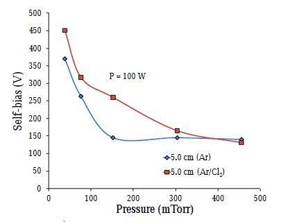
Finally, the type of gas that is used in the process will also yield a different result. Figure 2 below shows an example where the DC self-bias changes in a reactor where all variables are maintained, with the exception of the gas type. Due to lower electron density and higher electron temperature, the self-bias voltage in Ar/Cl2 plasma is higher compared to pure Ar plasma [3].
Figure 2: Self-bias dependence on the pressure for pure Ar and Ar/Cl2 mixture plasma for the same diameter electrode [3]
While the DC self-bias makes ion bombardment at the power electrode much more effective than at the ground electrode, some applications want to avoid the aggressive ion etching in order to prevent damage on ion-sensitive products. This can be done by taking the ground electrode as the product platform for a plasma etching (PE) process.
Plasma etching is widely used in mild etching processes and in plasma cleaning. The product is typically sitting on a grounded or floating potential holder and is completely immersed in the plasma cloud.
Especially in chemical plasmas, the exposure to a large quantity of radicals present in the plasma cloud can yield very satisfying results in terms of etch and/or surface activation.
SCI Automation Pte Ltd designs and manufactures very high-quality plasma systems which have the flexibility to switch between RIE and PE processes, both with very high uniformity in gas and RF distributions. Another configuration that we supply is downstream plasma where the ions and electrons are filtered out by a Faraday Grid, leaving a stream of free radicals and neutral species to the product for ion-free plasma. Downstream plasma can also be effectively used to filter out unwanted UV radiation. Special downstream designs allow us to create efficient “ion trap” and “UV trap” configurations. We will introduce this system and its applications in an upcoming blog.
SCI Automation Plasma Cleaners and etching systems combine the process strength, ion efficiency and throughput to qualify them as best in class equipment. With over 16 years of experience, SCI Automation is your qualified partner for plasma cleaning applications. Feel free to share with us your application requirements.
References:
[1] K. Nojiri, Dry Etching Technology for Semiconductors.
[2] M. J. Kushner, Monte-Carlo simulation of electron properties in rf parallel plate capacitively coupled discharges.
[3] J. Upadhyay, S. Popović, A.-M. Valente-Feliciano, L. Phillips and L. Vušković , Self-bias Dependence on Process Parameters in Asymmetric Cylindrical Coaxial Capacitively Coupled Plasma.

